by James Bainter © 2009 - 2012
Printable
Version
Introduction:
I got interested in the Python computer
language and started making multi-dimensional lists (matrix). This lead
me to wonder what application I could write using Python. I
decided
to try and solve a set of linear equations using Matrix Algebra. I
designed a Python program for analyzing both DC and AC circuits using
Mash and Node analysis. All went will until I wanted to analyze an
Active Circuit implemented with Operational Amplifiers (Op-Amps).
I searched the Web looking for information on writing Node
Equations for Active Circuits. I did find some papers written by
several professors saying that superposition could be used when current
and voltage generators in a given node/mash where a functions of
another node/mash. These professors also noted that many electronics
book authors have stated that superposition could not be used in this
situation. So, with this information, I decided to figure out how to
apply
my program to anlalyze an active filter I invented many years ago
called the "Bainter Filter" by some people on the Internet.
See article
published in the October 2, 1975 issue of Electronics
magazine.
How to Write the Equations:
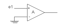
An Op-Amp Fig. 1
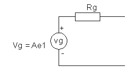
Op-Amp Thevenin equivalent voltage generator Fig. 2
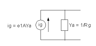
Op-Amp Norton equivalent current generator Fig. 3
All Op-Amps need to be converted to their Norton equivalent current generators as per Fig. 3 where e1 is the node voltage driving the Op-Amp, A is the open loop gain, and Ya is the output admittance of the amplifier.
Filter Schematic:
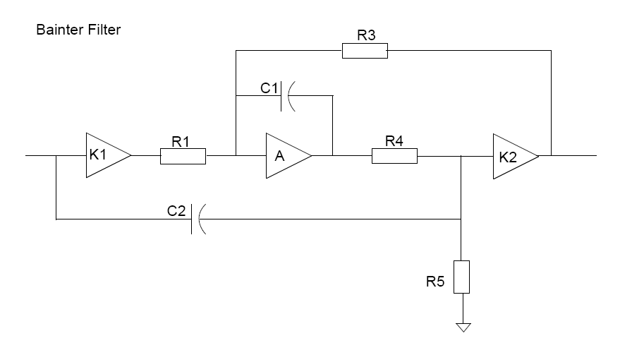
This filter contains three op-amps. Op-Amp K1 in an inverter (gain = -1.0). Op-Amp K2 is a unity gain buffer (gain = +1.0). The center Op-Amp is the one of interest. It has an open loop gain of -A as it is connected as an inverting amplifier.
We will next convert each Op-Amp to it's Norton current generator in order to write the node analysis equations.
Filter Node Schematic:
NOTE: All current generators point into their respective nodes. The sign of the Op-Amp connection is determined by the value of the symbols K1, A, and K2. For this filter K1 = -1.0, A (open loop gain) = - 100,000, and K2 = 1.0. Op-Amps K1 and A are inverting and K2 is non-inverting.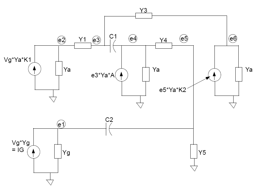
Filter Node Equations:
NOTE: Each value of capacitance must be multiplied by "s" where s = j*2*PI*f where "j" is used in Python to indicate a complex number and "f" is the frequency. The s's have been left out in order to simplify the equations below because the program I wrote did this operation for each frequency as the program runs.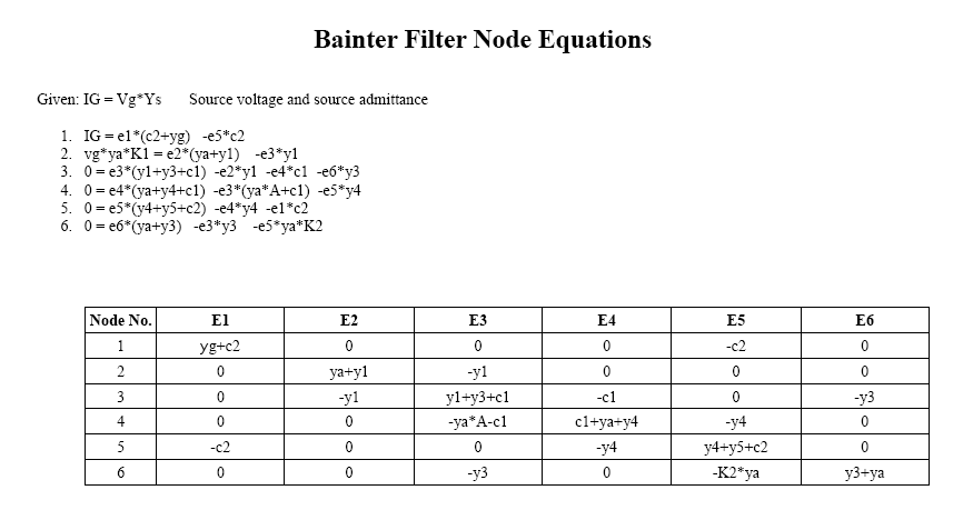
The voltage E4 at node 4 is a function of the voltage E3 at node 3; therefore the entry of -ya*A-c1 in cell 4-E3 in the above matrix. In this example, the amplifer gain has been defined as a negitive number. The mutual node four has a negative value because it is connected to the inverting (negative) input of the amplifer. If there would have been a mutual node for the positive input of the amplifer, it's repective equation would have a positive sign. If the gain is defined with a positive value the mutual node equations will have signs opposite from this example.
Gain sign negative: mutual equation sign same as amplifer input sign.
Gain sign positive: mutual equation sign opposite of amplifer input sign.
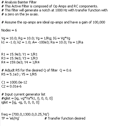
Filter Spec's (Component values and frequency sweep range)
Filter Program Test Results:
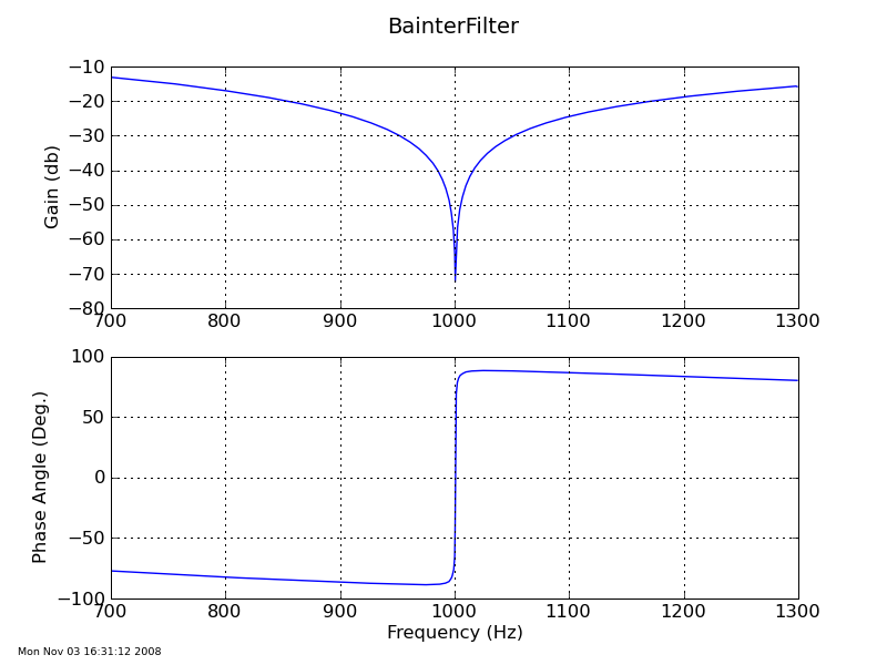
Following is a graph of the filter tuned to 1000 Hz. The plot was made by the Python program I wrote using the equations in this document.